$380.00 Original price was: $380.00.$230.00Current price is: $230.00.
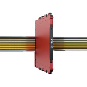
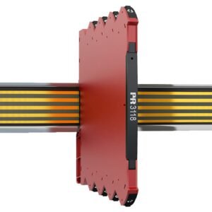
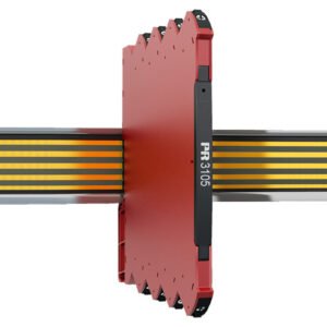
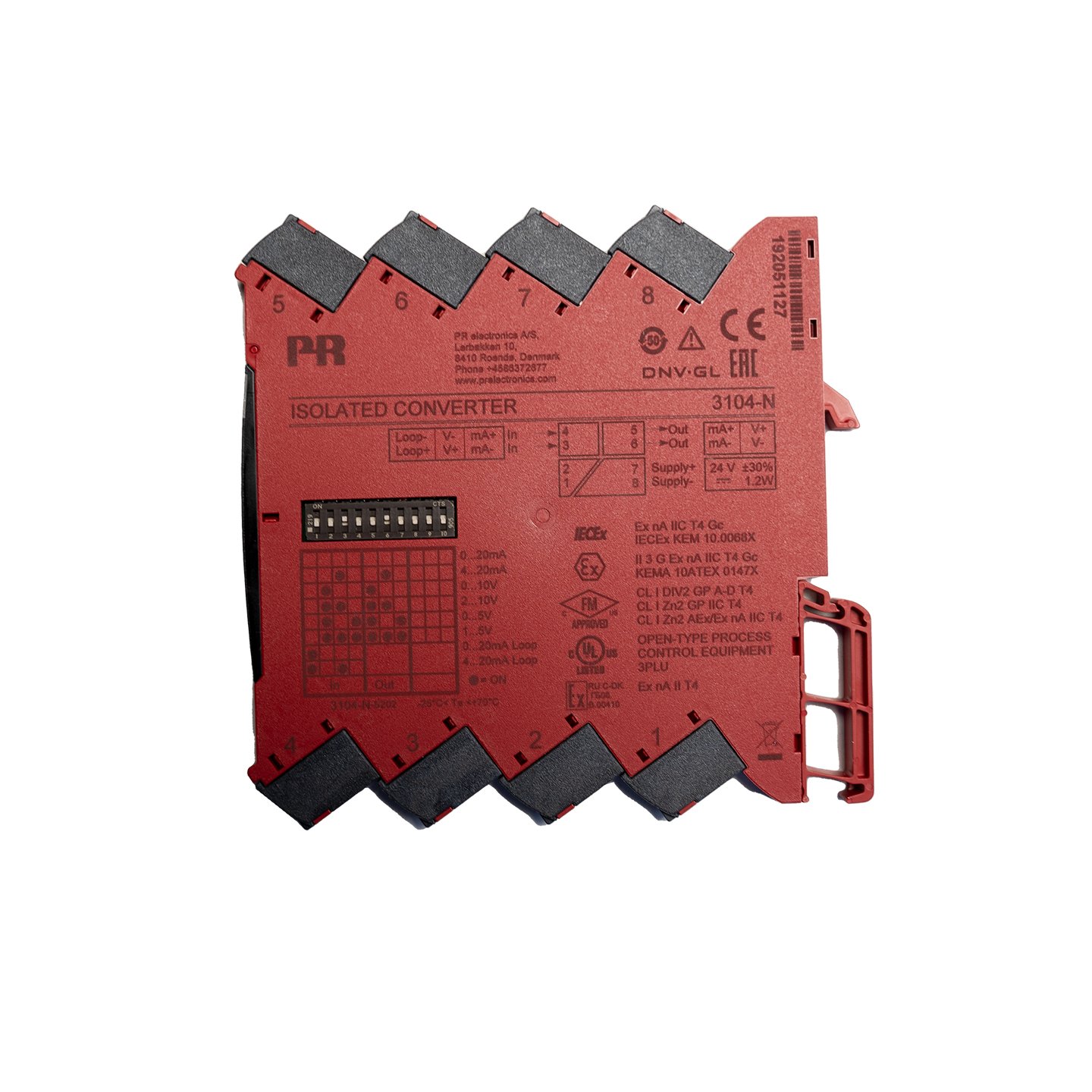
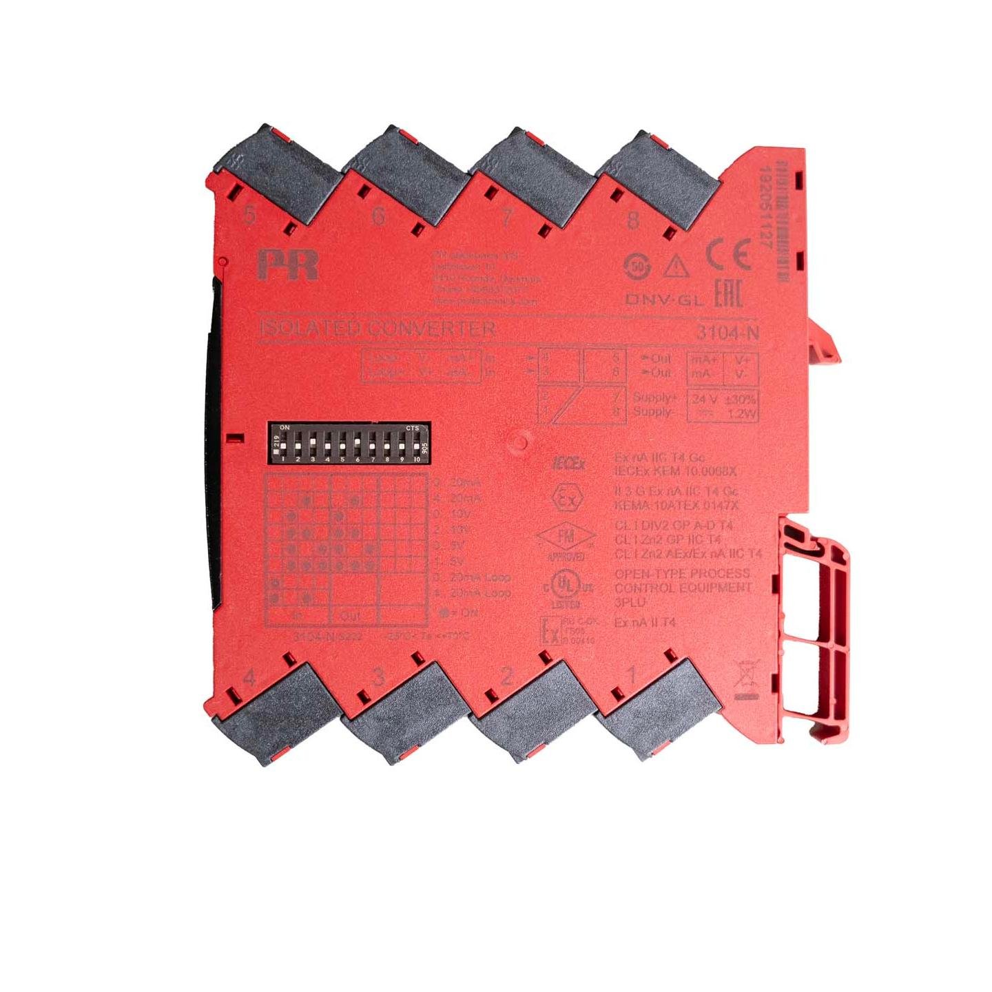
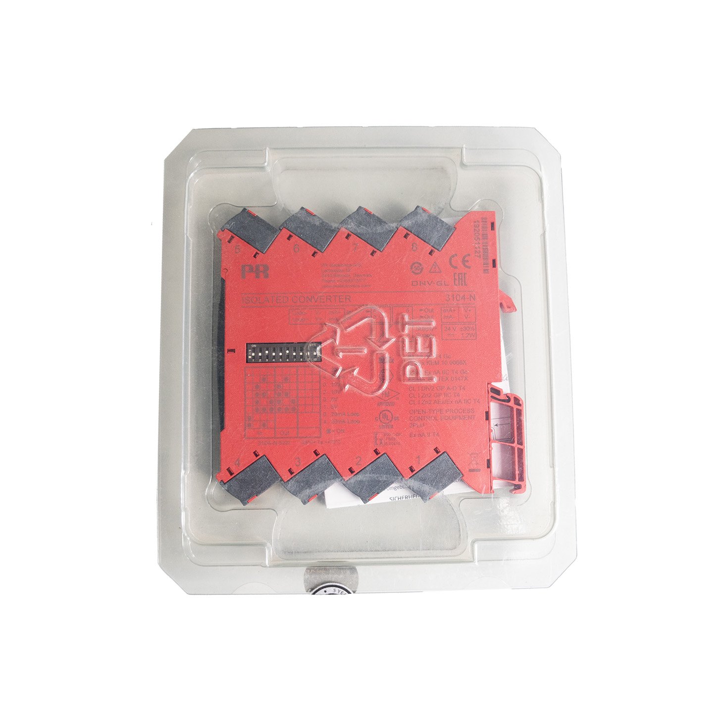
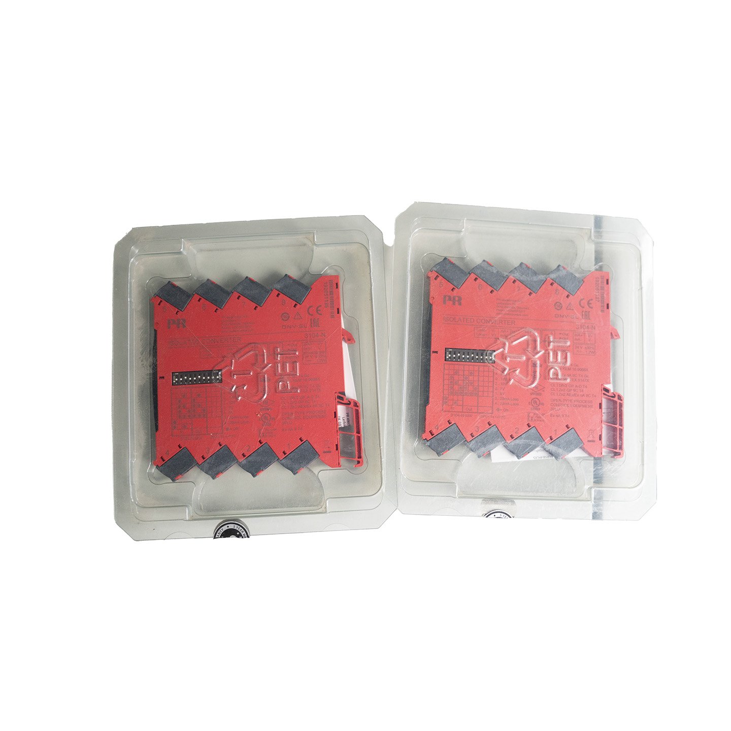
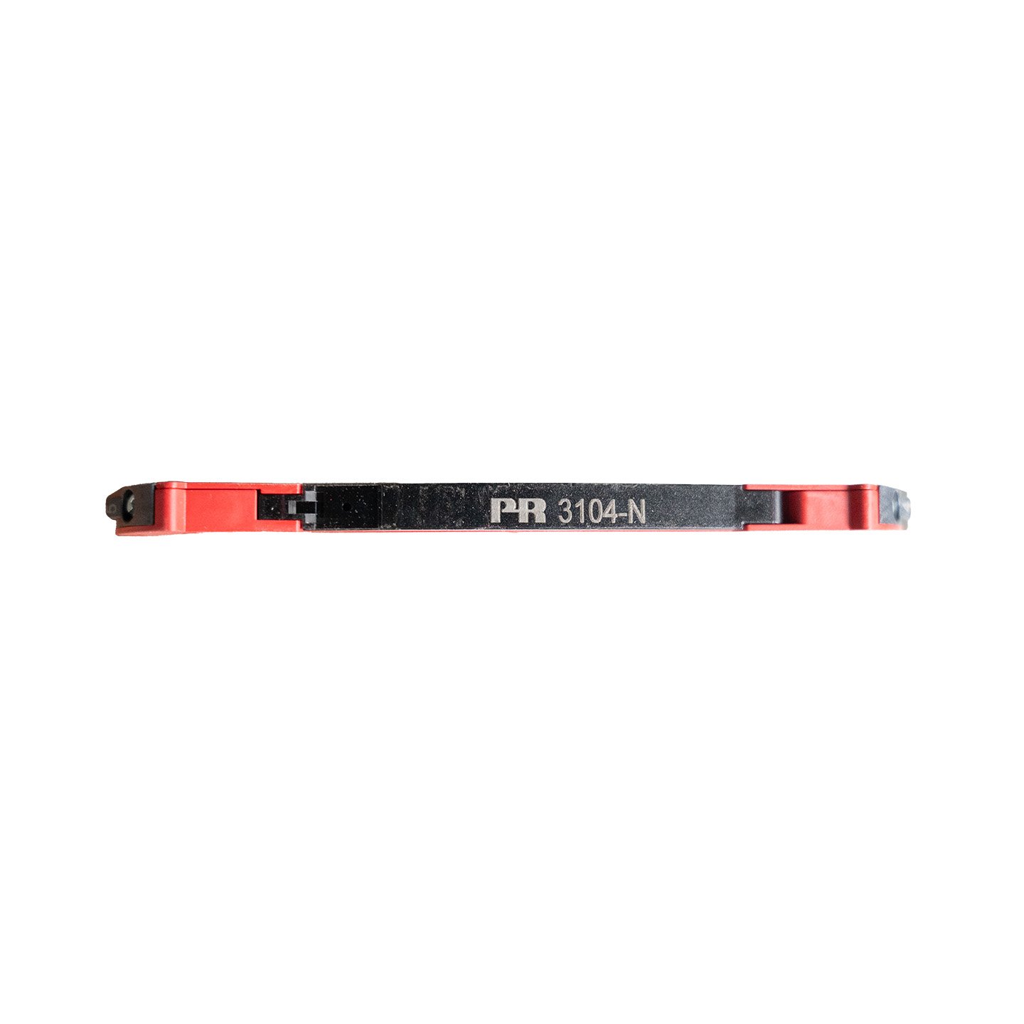
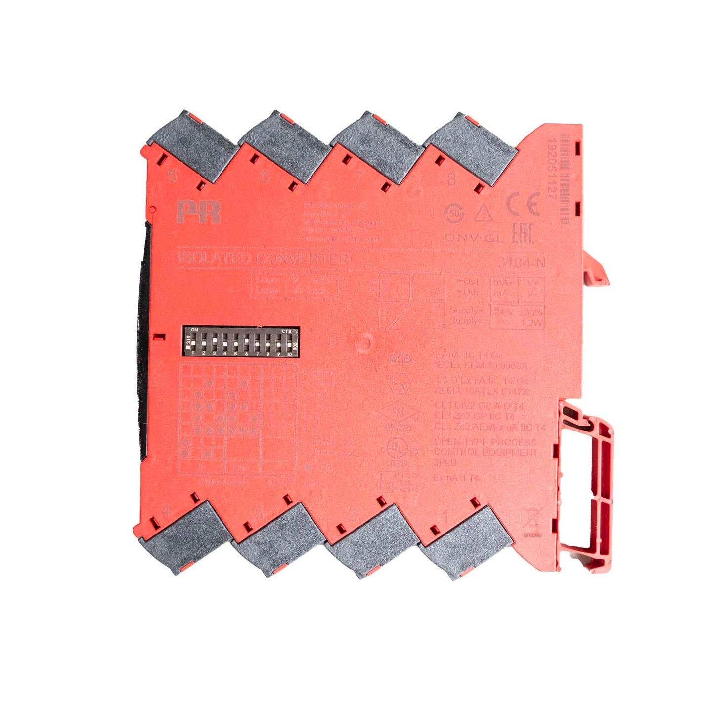
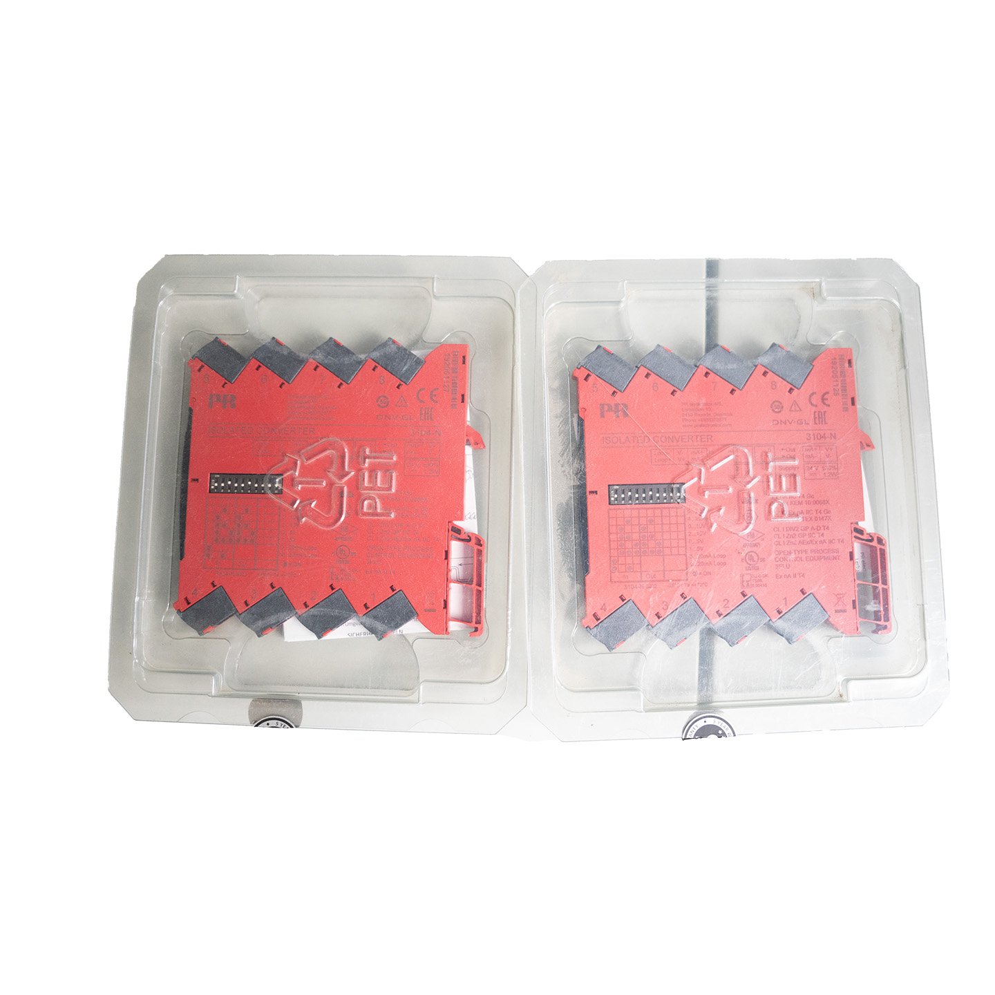
PR 3104-N Signal Converter, brand new and unused, complete with original packaging, in perfect condition, fully functional, with all specifications included. Suitable for use in industrial automation, PLCs, and control systems.

| Operating temperature | -25°C to +70°C |
| Storage temperature | -40°C to +85°C |
| Calibration temperature | 20…28°C |
| Relative humidity | < 95% RH (non-cond.) |
| Protection degree | IP20 |
| Installation in | Pollution degree 2 & meas. / overvoltage cat. II |
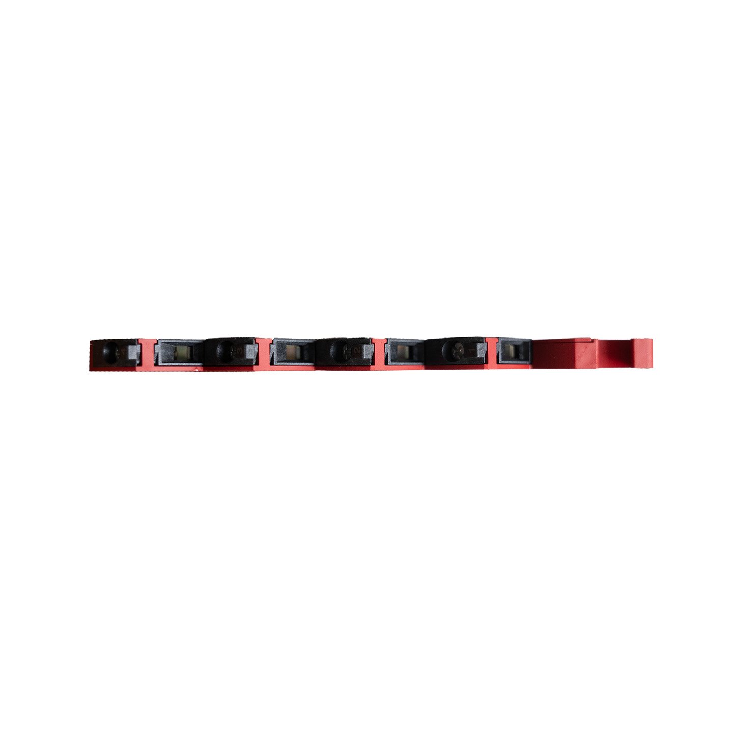
| Dimensions (HxWxD) | 113 x 6.1 x 115 mm |
| Weight approx. | 70 g |
| DIN rail type | DIN EN 60715/35 mm |
| Wire size | 0.13…2.5 mm2 / AWG 26…12 stranded wire |
| Screw terminal torque | 0.5 Nm |
| Vibration | IEC 60068-2-6 |
| 2…25 Hz | ±1.6 mm |
| 25…100 Hz | ±4 g |
Supply |
|
| Supply voltage | 16.8…31.2 VDC |
| Max. required power | ≤ 1.2 W |
| Max. power dissipation | 0.55 W |
Isolation voltage |
|
| Isolation voltage, test / working | 2.5 kVAC / 300 VAC (reinforced) |
| Zone 2 / Div. 2 | 250 VAC |
Response time |
|
| Response time (0…90%, 100…10%) | < 7 ms |
| Programming | DIP switches |
| Signal / noise ratio | > 60 dB |
| Cut-off frequency (3 dB) | > 100 Hz |
| Signal dynamics, input | Analog signal chain |
| Signal dynamics, output | Analog signal chain |
| Accuracy | Better than 0.05% of selected range |
| Temperature coefficient | < ±0.01% of span / °C |
| EMC immunity influence | < ±0.5% of span |
| Extended EMC immunity: NAMUR NE21, A criterion, burst | < ±1% of span |
Current input |
|
| Measurement range | 0…23 mA |
| Programmable measurement ranges | 0…20 and 4…20 mA |
| Input voltage drop | < 1.5 VDC |
| Input resistance | Nom. 20 Ω + PTC 50 Ω |
| 2-wire transmitter supply | > 17 V / 20 mA |
Voltage input |
|
| Measurement range | 0…10.25 V |
| Functional range | 0…11.5 V / 0…5.75 V |
| Programmable measurement ranges | 0/1…5 and 0/2…10 V |
| Input resistance | ≥ 500 kΩ |
Current output |
|
| Signal range | 0…23 mA |
| Programmable signal ranges | 0 / 4…20 mA |
| Load (@ current output) | ≤ 600 Ω |
| Load stability | ≤ 0.002% of span / 100 Ω |
| Current limit | ≤ 28 mA |
Voltage output |
|
| Signal range | 0…10 VDC |
| Programmable signal ranges | 0/1…5 and 0/2…10 V |
| Load (@ voltage output) | ≥ 10 kΩ |
| of span | = of the DIP switch selected output range |
| ATEX | II 3 G Ex ec IIC T4 Gc |
| IECEx | Ex ec IIC T4 Gc |
| FM, US | Cl. I, Div. 2, Gp. A, B, C, D T4 or Cl. I, Zone 2, AEx nA IIC T4 |
| FM, CA | Cl. I, Div. 2, Gp. A, B, C, D T4 or Cl. I, Zone 2, Ex nA IIC T4 |
| EAC Ex | 2Ex nA IIC T4 Gc X |
| EMC | 2014/30/EU & UK SI 2016/1091 |
| LVD | 2014/35/EU & UK SI 2016/1101 |
| ATEX | 2014/34/EU & UK SI 2016/1107 |
| RoHS | 2011/65/EU & UK SI 2012/3032 |
| EAC | TR-CU 020/2011 |
| EAC Ex | TR-CU 012/2011 |
| ATEX | KEMA 10ATEX0147 X |
| IECEx | KEM 10.0068X |
| UKEX | DEKRA 21UKEX0055X |
| c FM us | FM17US0004X / FM17CA0003X |
| c UL us, UL 61010-1 | E314307 |
| CCC | 2020322310003554 |
| EAC Ex | EAEU KZ 7500361.01.01.08756 |
| DNV Marine | TAA00001RW |